EP2C5T144+ESP-32(4)WifiスケッチにSPIを追加
前回で手順1番目が終わり、今回は作業手順の2番目、ESP-WROOM-32のSPIです。
- Windows PC上でFPGAを操作するためのバイト列を作ってWifiで送信
- ESP-WROOM-32で受信したバイト列をSPIでFPGAに送信
- FPGAで受信したバイト列をデコードしてボード上のLEDを点滅
Windows PC →(Wifi)→ ESP-WROOM-32 →(SPI)→ EP2C5T144の内、SPIの部分を実装します。
#include <SPI.h>
#include <WiFi.h>

/* Set these to your desired credentials. */
//const char *ssid = "ESPap";
//const char *password = "thereisnospoon";

const char* ssid     = "your-ssid";
const char* password = "your-password";

WiFiServer server(2002);
WiFiClient client;

#define SPI_BUF_LEN 1024
byte spiBuf[SPI_BUF_LEN];
byte spiReadBuf[SPI_BUF_LEN];

void setup() {
  Serial.begin(57600);

  SPI.begin();
  SPI.setFrequency(24000000);
  SPI.setDataMode(SPI_MODE1);
  SPI.setBitOrder(MSBFIRST);
  pinMode(SS, OUTPUT);
  digitalWrite(SS, HIGH);

//  Serial.println();
//  Serial.print("Configuring access point...");
//  /* You can remove the password parameter if you want the AP to be open. */
//  WiFi.mode(WIFI_AP);
//  WiFi.softAP(ssid, password);
//  IPAddress myIP = WiFi.softAPIP();
//  Serial.print("AP IP address: ");
//  Serial.println(myIP);

  Serial.println();
  Serial.print("Connecting to ");
  Serial.println(ssid);
  //WiFi.mode(WIFI_STA);  // Disable Access Point
  WiFi.begin(ssid, password);
  while (WiFi.status() != WL_CONNECTED) {
    delay(500);
    Serial.print(".");
  }
  Serial.println("");
  Serial.println("WiFi connected");
  Serial.println("IP address: ");
  Serial.println(WiFi.localIP());

  server.begin();
  Serial.println("Server started");
}

void loop() {
  if (!client.connected()) {
    // try to connect to a new client
    client = server.available();
  } else {
    // read data from the connected client
    int n = client.available();
    if (n > 0) {
      //Serial.print("available: ");
      //Serial.println(n);
      if (n > SPI_BUF_LEN) {
        n = SPI_BUF_LEN;
      }

      // transfer data to/from SPI
      client.readBytes(spiBuf, n);
      digitalWrite(SS, LOW);
      SPI.transferBytes(spiBuf, spiReadBuf, n);
      digitalWrite(SS, HIGH);

      // return data to client
      client.write(spiReadBuf, n);
    }
  }
}
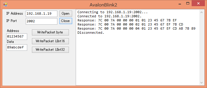
ESP-WROOM-32のMISO(ピンD19)とMOSI(ピンD23)を繋いでループバックにしています。動作確認用のWindowsアプリは前回と同じで結果の表示内容も前回と同じになります。
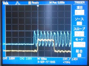
オシロスコープで信号を確認しましたが、オシロスコープの帯域が足りません。配線がいい加減なせいなのか、オシロスコープのせいなのか判りません。青色がSCLK、黄色がMOSIです。
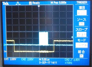
SSラインの様子も見てみました。16バイトをまとめて送っている例です。青色がSCLK、黄色がSSです。