EP2C5T144+ESP-32(3)Wifiスケッチ
前回に続き作業手順の1番目、WindowsアプリとESP-WROOM-32スケッチをWifiで接続します。
- Windows PC上でFPGAを操作するためのバイト列を作ってWifiで送信
- ESP-WROOM-32で受信したバイト列をSPIでFPGAに送信
- FPGAで受信したバイト列をデコードしてボード上のLEDを点滅
Windows PC →(Wifi)→ ESP-WROOM-32 →(SPI)→ EP2C5T144の内、Wifiの部分を実装します。
まずはESP-WROOM-32側のArduinoスケッチです。
#include <WiFi.h>

/* Set these to your desired credentials. */
//const char *ssid = "ESPap";
//const char *password = "thereisnospoon";

const char* ssid     = "your-ssid";
const char* password = "your-password";

WiFiServer server(2002);
WiFiClient client;

#define PACKET_BUF_LEN 1024
byte packetBuf[PACKET_BUF_LEN];

void setup() {
  Serial.begin(57600);

//  Serial.println();
//  Serial.print("Configuring access point...");
//  /* You can remove the password parameter if you want the AP to be open. */
//  WiFi.mode(WIFI_AP);
//  WiFi.softAP(ssid, password);
//  IPAddress myIP = WiFi.softAPIP();
//  Serial.print("AP IP address: ");
//  Serial.println(myIP);

  Serial.println();
  Serial.print("Connecting to ");
  Serial.println(ssid);
  //WiFi.mode(WIFI_STA);  // Disable Access Point
  WiFi.begin(ssid, password);
  while (WiFi.status() != WL_CONNECTED) {
    delay(500);
    Serial.print(".");
  }
  Serial.println("");
  Serial.println("WiFi connected");
  Serial.println("IP address: ");
  Serial.println(WiFi.localIP());

  server.begin();
  Serial.println("Server started");
}

void loop() {
  if (!client.connected()) {
    // try to connect to a new client
    client = server.available();
  } else {
    // read data from the connected client
    int n = client.available();
    if (n > 0) {
      //Serial.print("available: ");
      //Serial.println(n);
      if (n > PACKET_BUF_LEN) {
        n = PACKET_BUF_LEN;
      }

      // loopback
      client.readBytes(packetBuf, n);
      client.write(packetBuf, n);
    }
  }
}
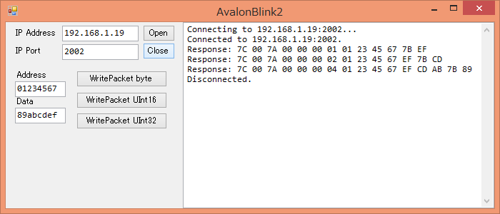
ソケット通信機能を追加した動作確認用のWindowsアプリの画面です。ESP-WROOM-32は受信したバイト列をそのまま返し、アプリはそれを表示しています。